We are working hard to bring you the best quality products in the industry. That is why we only partner with the most reliable brands you will find anywhere.
We are here not only to help you source the best parts for your hydraulic, pneumatic, electromechanical, and other industrial applications, but also to support your operations with services that make your job easy and your business more efficient.
We have been solving hydraulic and pneumatic challenges for over 60 years! Many of our Technology Managers, engineers, and leaders previously worked for leading motion and flow product manufacturers like Parker Hannifin. We know our products, and we understand your industry. Take advantage of our expertise – we'll be thrilled to help you
We Are Parker Chomerics DistributorChomerics Division is a global leader in the development and application of electrically conductive and thermal interface materials for electronics, life science, aerospace, automotive, and other markets. |
|


Products
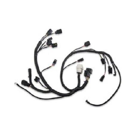
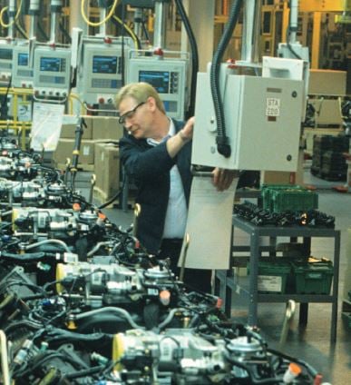
Harness Solutions
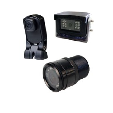
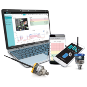
& Video
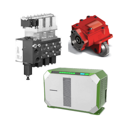
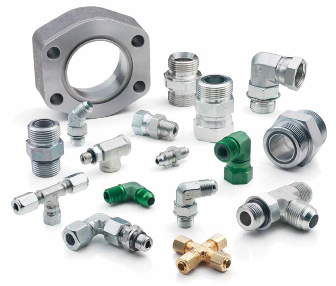
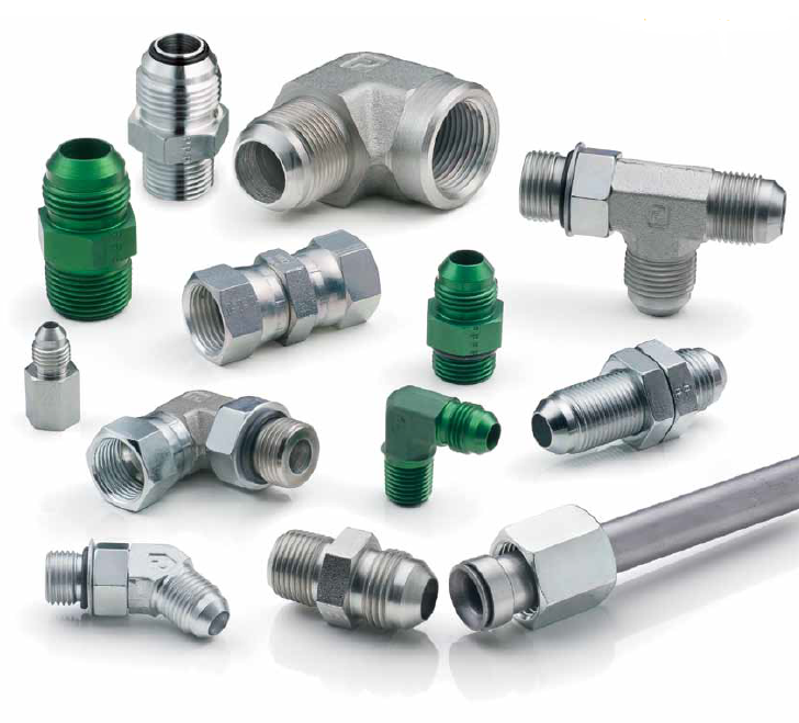
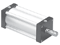
Hydraulics
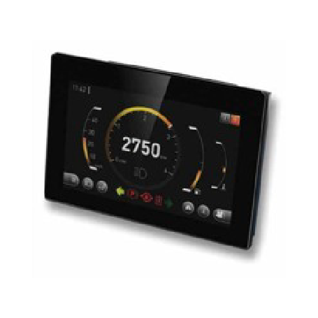
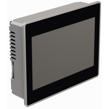
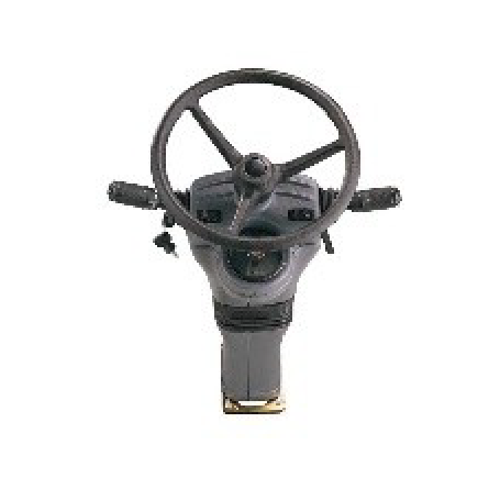
HMI Centers
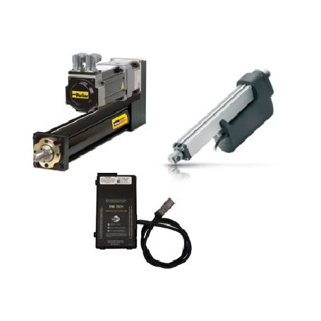
& Cylinders
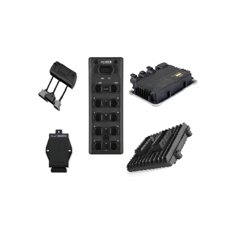
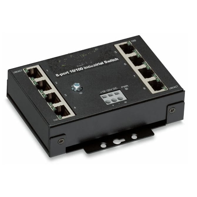
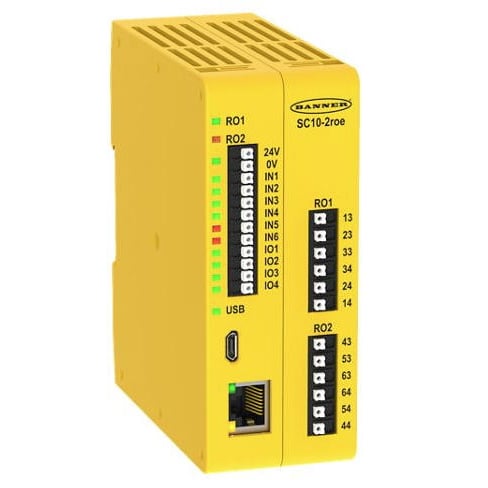
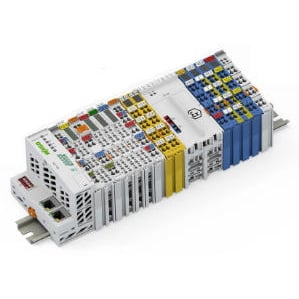
I/O Modules
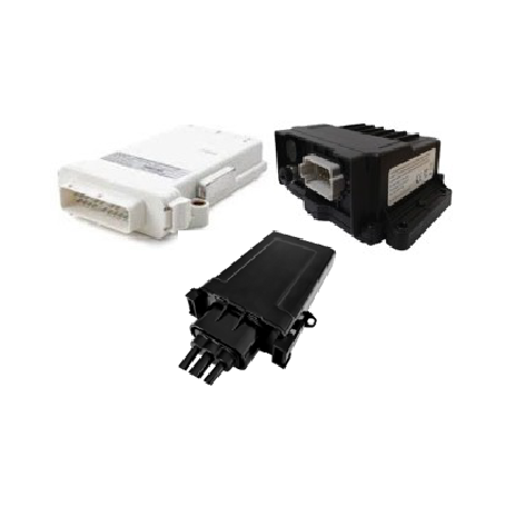
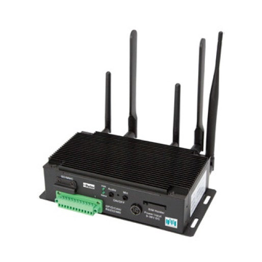
Telematics
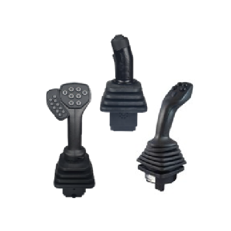
& Levers
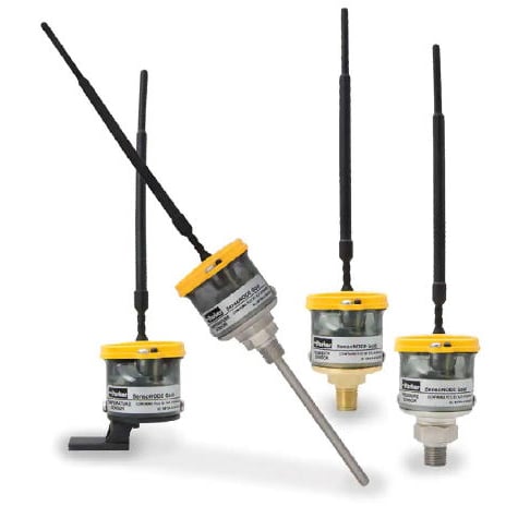
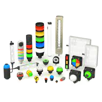
Beacons
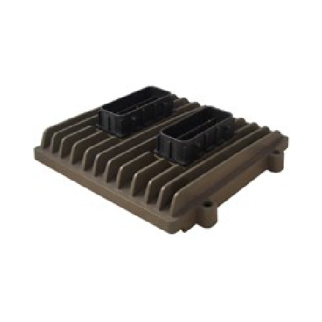
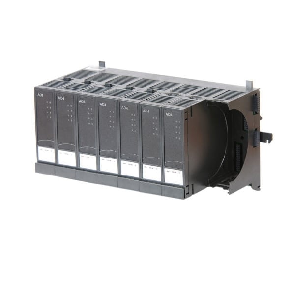
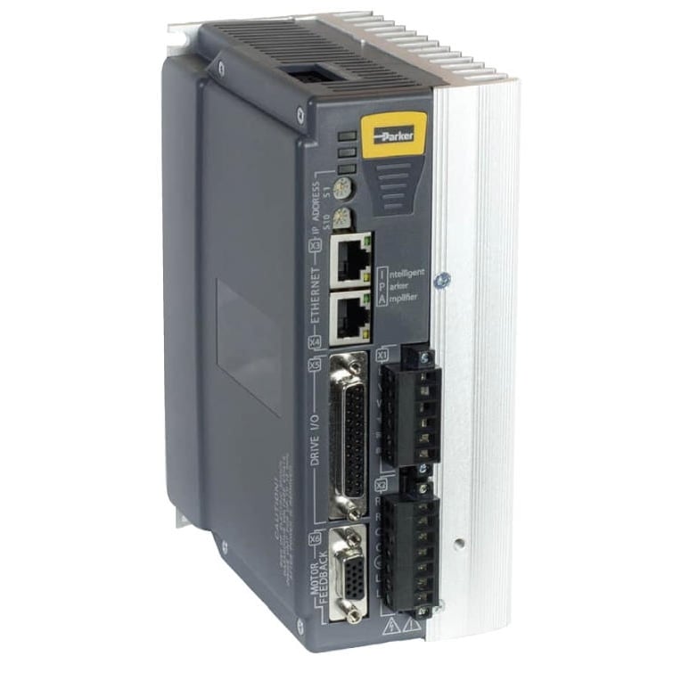
Controllers
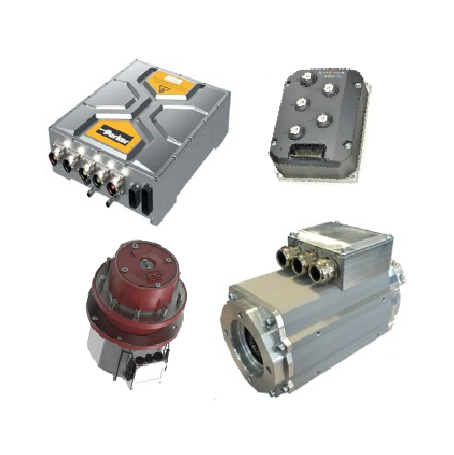
& Drives
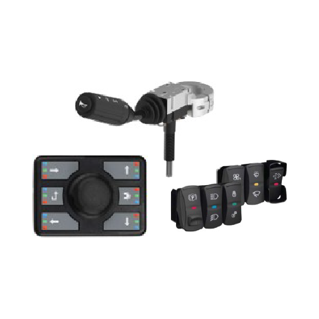
Interfaces
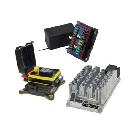
Management
& Switches
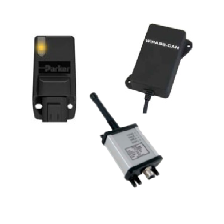
Radio Controls
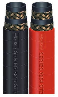
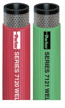
Hoses
Assemblies
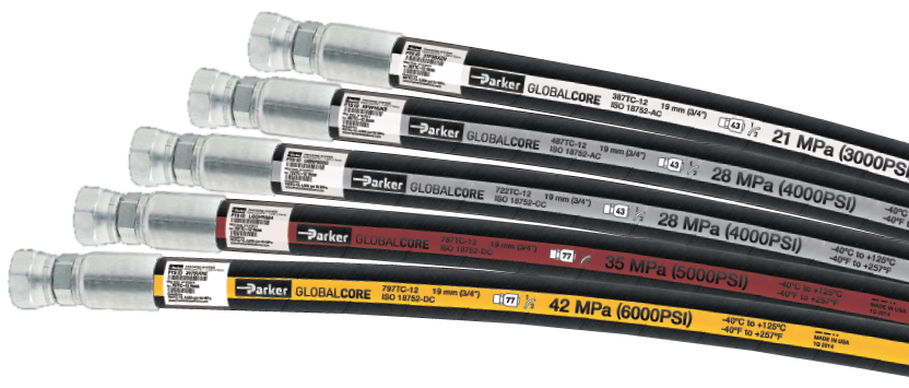
Hydraulic
Hoses
Hoses
Hoses
/PTFE Hoses
1-Wire
Hoses
2-Wire
Hoses
4-Wire
Hoses
6-Wire
Hoses
Fiber-Reinforced
Hoses
Metal Hoses
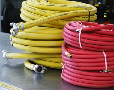
Purpose Hoses
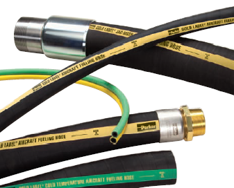
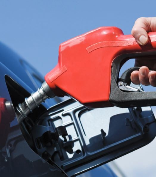
Fuel Hoses
Hoses
Hoses
Hoses
Hoses
Hoses
Hoses
Hoses
Dispenser Hoses
Hoses
Hoses
Hoses
Accessories