
JIC Tube End Assembly | Parker Triple-Lok/Triple-Lok 2 Assembly
For leak-free performance, the JIC fitting assembly requires the following steps:
|
|
|
")
Flaring
NOTE: Improper flaring or installation causes over half of the leakage instances associated with flared fittings. Follow the installation steps below carefully to avoid this common cause of leakage.
Several tube end flaring methods are available. They involve use of either hand flaring or power flaring tools. Various tools for flaring are shown in Parker Catalog 4300 - Industrial Tube Fittings (click to download PDF) in the Fabrication Equipment section.
The preferred method is power flaring, because it is quicker and produces more accurate and consistent flares compared to hand flaring. Hand flaring should be limited to places where power flaring tools are not readily available. The Parker Parflange machines also flare tubes with an orbital flaring process and provide the best flare for stainless steel tube.
IMPORTANT:
Use only seamless or welded and drawn tube that is fully annealed for flaring and bending. For the recommended minimum and maximum tube wall thickness for Parker Triple-Lok fittings, please see the table below.
|
Fitting Dash Size |
Wall Thickness - Inch Tube |
Wall Thickness - Metric Tube |
||
|
O.D. (in) |
Wall Thickness Min - Max (in) |
O.D. (mm) |
Wall Thickness Min - Max (mm) |
|
| -2 | 1/8 | 0.010 - 0.035 | - | - |
| -3 | 3/16 | 0.010 - 0.035 | - | - |
| -4 | 1/4 | 0.020 - 0.065 | 6.0 | 0.5 - 2.0 |
| -5 | 5/16 | 0.020 - 0.065 | 8.0 | 0.5 - 2.0 |
| -6 | 3/8 | 0.020 - 0.065 | 10.0 | 0.5 - 2.0 |
| -8 | 1/2 | 0.028 - 0.083 | 12.0 | 1.0 - 2.0 |
| -10 | 5/8 | 0.035 - 0.095 | 14.0 | 1.0 - 2.5 |
| -10 | 5/8 | 0.035 - 0.095 | 15.0 | 1.0 - 2.5 |
| -10 | 5/8 | 0.035 - 0.095 | 16.0 | 1.0 - 2.5 |
| -12 | 3/4 | 0.035 - 0.109 | 18.0 | 1.0 - 3.0 |
| -12 | 3/4 | 0.035 - 0.109 | 20.0 | 1.0 - 3.0 |
| -14 | 7/8 | 0.035 - 0.109 | 22.0 | 1.0 - 3.0 |
| -16 | 1 | 0.035 - 0.120 | 25.0 | 1.0 - 3.0 |
| -20 | 1-1/4 | 0.049 - 0.120 | 30.0 | 1.5 - 3.0 |
| -20 | 1-1/4 | 0.049 - 0.120 | 32.0 | 1.5 - 3.0 |
| -24 | 1-1/2 | 0.049 - 0.120 | 38.0 | 1.5 - 3.0 |
| -32 | 2 | 0.058 - 0.134 | 50.0 | 1.5 - 3.5 |
NOTE:
Prior to flaring, determine the tube length allowance using the table below. This tube length allowance should be added to the cut tube length to allow for the reduction in tube length caused by flaring.
| Nominal Tube O.D | A | |
| Inch | Metric | |
| 1/8 | - | 0.07 |
| 3/16 | - | 0.08 |
| 1/4 | 6 | 0.09 |
| 5/16 | 8 | 0.08 |
| 3/8 | 10 | 0.08 |
| 1/2 | 12 | 0.12 |
| 5/8 | 14, 15, 16 | 0.13 |
| 3/4 | 18, 20 | 0.15 |
| 7/8 | 22 | 0.15 |
| 1 | 25 | 0.15 |
| 1-1/4 | 30, 32 | 0.20 |
| 1-1/2 | 38 | 0.18 |
| 2 | 42 | 0.28 |
 |
 |
TIP: Be sure to insert a nut and a sleeve in proper sequence and orientation before flaring either end of bent tube, or second end of a straight tube. |
To flare the tube end, consult your flaring tooling manual. Tube fabrication tools, including flaring tools, are available from Parker Catalog 4300 Section S.
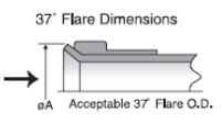
JIC flare inspection
The table below shows the proper flare dimensions for JIC fittings:
|
Inch Tube O.D. (in) |
Metric Tube O.D. (mm) |
37° Flare Diameter ØA (in) |
| 1/4 | 6 | .340/.360 |
| 5/16 | 8 | .400/.430 |
| 3/8 | 10 | .460/.490 |
| 1/2 | 12 | .630/.660 |
| 5/8 | 15 & 16 | .760/.790 |
| 3/4 | 18 & 20 | .920/.950 |
| 1 | 25 | 1.170/1.200 |
| 1-1/4 | 30 & 32 | 1.480/1.510 |
| 1-1/2 | 38 | 1.700/1.730 |
| The sleeve can also be used for a quick check of the flare dimensions: |  |
 |
Over-flaring causes tube nut thread interference, either preventing assembly altogether, or giving a false sense of joint tightness resulting in leakage. Under-flaring reduces contact area causing excessive nose collapse and leakage. In extreme cases, tube can pull out under pressure. |
Inspect the JIC flare to make sure it is reasonably square and concentric with the tube cross-section and that its surface is smooth, free of rust, scratches, splits, weld beads, draw marks, embedded chips, burrs and dirt.
If the flare does not meet the above requirements, cut it off, determine the probable cause from the troubleshooting guide, take corrective action and re-flare.
Installation
NOTE: Improper flaring or installation causes over half of the leakage with flared fittings. Follow the installation steps below carefully to avoid this common cause of leakage.
Do not force an improperly bent tube into alignment or draw-in too short a tube using the nut. It puts undesirable strain on the joint, eventually resulting in leakage.
Align the tube on the flare (nose) of the fitting body and tighten the nut by using either the “Flats from Wrench Resistance (FFWR)" or Torque method.
Flats from Wrench Resistance (FFWR) Method
- Tighten the nut lightly with a wrench (approximately 30 in.lb.), clamping the tube flare between the fitting nose and the sleeve. This is considered the Wrench Resistance (WR) position.
- Starting Wrench Resistance position, tighten the nut further by the number of flats from Table below. A flat is referred to as one side of the hexagonal tube nut and equates to 1/6 of a turn.
The FFWR method is preferred to the torque method and should be used whenever possible. FFWR method circumvents the effects of differences in plating, lubrication, surface finishes, etc., that affect the torque value required to achieve proper joint. Always use FFWR method where the plating combination of components is not known, and during maintenance and repair where the components may be oily.
Wherever possible, at the initial wrench resistance position, mark one of the flats of the nut and extend the mark on to the body hex with a permanent type ink marker. This will provide a visual reference when you tighten the nut the required number of flats (see the table below).
|
SAE Dash Size |
Thread Size |
Assembly Torque* (+10% -0) |
Tube Connection FFWR |
Swivel Nut or Hose Connection FFWR |
|
| in. lb. | ft. lb. | ||||
| -2 | 5/16-24 | 35 | 3 | - | - |
| -3 | 3/8-24 | 65 | 5 | - | - |
| -4 | 7/16-20 | 155 | 13 | 2-1/2 | 2 |
| -5 | 1/2-20 | 165 | 14 | 2 | 2 |
| -6 | 9/16-18 | 265 | 22 | 2 | 1-1/2 |
| -8 | 3/4-16 | 505 | 42 | 2 | 1-1/2 |
| -10 | 7/8-14 | 720 | 60 | 1-1/2 | 1-1/2 |
| -12 | 1 1/16-12 | 1000 | 84 | 1-1/2 | 1-1/4 |
| -14 | 1 3/16-12 | 1200 | 100 | 1-1/2 | 1-1/4 |
| -16 | 1 5/16-12 | 1415 | 118 | 1-1/2 | 1 |
| -20 | 1 5/8-12 | 2015 | 168 | 1 | 1 |
| -24 | 1 7/8-12 | 2340 | 195 | 1 | 1 |
| -32 | 2 1/2-12 | 3180 | 265 | 1 | 1 |
| -40 | 3-12 | - | - | 1 | 1 |
- Assembly Torque: Torque values are for unlubricated carbon steel components and properly lubricated stainless steel components. For stainless steel, a lubricant such as Permatex Anti-Seize Lubricant is recommended to prevent galling.
- FFWR: The Flats From Wrench Resistance or “Flats” method is recommended for steel, stainless steel and brass components.
- Torque and FFWR: Torques and FFWR shown in the chart are for use with the tube materials, wall thickness, etc. recommended by Parker Hannifin Tube Fittings Division for use with Parker Triple-Lok fittings.
Torque Method
With proper tube flare alignment with the nose of the fitting, tighten the nut to appropriate torque value (see the table above). This method is fast and accurate when preset torque wrenches are used. Consistent component selection is recommended so that the effects of dissimilar plating is not an adverse factor in joint integrity. This makes it desirable for high production assembly lines. However, a joint assembled using the torque method can only be checked for proper tightening by tightening it again.
Note: This method should not be used if the type of plating on the fitting and mating parts (sleeve + nut or hose swivel) is not known. The torque method should not be used for lubricated or oily parts as improper clamping forces may result. Over-tightening and fitting damage may occur as a result.
