
Parker Seal-Lok fittings assembly instructions
The proper assembly of the Seal-Lok and Seal-Lok Lite fitting requires several steps, each important in guaranteeing a leak-free connection and a long service life:
 |
|
Flanging
The flanging method requires the use of an appropriate forming machine to create the flange or flat face on the tube end. Since the flat face of the flanged tube seals against the O-ring within the fitting groove, it is important that this surface be relatively smooth. Proper tube end preparation (cutting, deburring and cleaning) will help accomplish this goal. The Parker Parflange® machines utilize an orbital cold forming process to produce a flat, smooth, rigidly supported 90° sealing surface on the tube end.
Step 1: Determine the extra cut-off length required for the Parflange process by referring to the tables below. Choose the table to use depending on your tubing - either inch or metric. Keep in mind that each table is only a guide. Variations in tube wall thickness and inconsistency in quality of tube cut-off may affect actual dimensions. You should verify actual extra tube cut-off length with one or two flanges prior to large scale flanging.
|
|

| Tube O.D. (in) | Tube Wall Thickness - Inch | ||||||||||
| .028 | .035 | .049 | .065 | .083 | .095 | .109 | .120 | .134 | .156 | .188 | |
| 1/4 | 3/16 | 13/64 | 7/32 | ||||||||
| 3/8 | 5/32 | 3/16 | 13/64 | 15/64 | 1/4 | ||||||
| 1/2 | 9/64 | 9/64 | 3/16 | 13/64 | 9/32 | 19/64 | 19/64 | ||||
| 5/8 | 11/64 | 3/16 | 13/64 | 1/4 | 17/64 | 17/64 | |||||
| 3/4 | 11/64 | 3/16 | 7/32 | 7/32 | 1/4 | 17/64 | 9/32 | ||||
| 1 | 3/16 | 13/64 | 13/64 | 15/64 | 1/4 | 19/64 | |||||
| 1-1/4 | 11/64 | 13/64 | 13/64 | 15/64 | 1/4 | 19/64 | 19/64 | 21/64 | |||
| 1-1/2 | 13/64 | 15/64 | 15/64 | 17/64 | 17/64 | 19/64 | 23/64 | 3/8 | |||
| Tube O.D. (in) | Metric Tube Outside Diameter - (mm) |
||||||||
| 6 | 8 | 10 | 12 | 16 | 20 | 25 | 30 | 38 | |
| 1.0 |
3/16 5.2 |
7/32 5.7 |
1/8 3.1 |
5/32 4.1 |
9.64 3.6 |
||||
| 1.5 |
17.64 6.7 |
15/64 5.9 |
13.64 5.1 |
7/32 5.4 |
11/64 4.2 |
||||
| 2.0 |
13.64 5.3 |
15/64 6.1 |
3/16 4.9 |
7/32 5.4 |
15/64 6.1 |
17/64 6.6 |
9/32 7.2 |
||
| 2.5 |
17/64 6.7 |
7/32 5.5 |
15/64 6.1 |
1/4 6.4 |
19/64 7.6 |
||||
| 3.0 |
15/64 5.8 |
17/64 6.7 |
9/32 7.2 |
5/16 7.9 |
19/64 7.7 |
||||
| 3.5 |
17/64 6.9 |
19/64 7.5 |
21/64 8.5 |
||||||
| 4.0 |
9/32 7.2 |
5/16 8.0 |
11/32 8.6 |
11/32 8.7 |
|||||
| 5.0 |
11/32 8.8 |
3/8 9.4 |
|||||||
Step 2: Select the proper tooling for the tube size. The tube OD, wall thickness and material must be known for proper selection. (For assistance with tooling selection, see Parker's ToolSpec selector app.)
Note: Another consideration prior to flanging is the minimum straight length to the start of a 90° bend.

* L1 refers to the minimum straight length to the start of the tube bend.
** L2 refers to the minimum centerline dimension necessary for a 90° bent tube to clear the frame of the Parker Parflange 1040
|
Tube O.D. Inch Sizes |
Tube O.D. Metric Sizes |
L* | L1** | ||
| (in) | (mm) | (in) | (mm) | ||
| 1/4 |
6 |
1-5/16 |
35 |
3-1/8 |
79 |
| 5/16 |
8 |
1-5/16 |
35 |
3-5/32 |
80 |
| 3/8 |
10 |
1-5/16 |
40 |
3-3/16 |
81 |
| 1/2 |
12 15 |
1-3/8 1-3/8 |
40 40 |
3-1/4 3-5/16 |
82 84 |
| 5/8 |
16 18 |
1-1/2 1-5/8 |
41 42 |
3-5/16 3-11/32 |
84 85 |
| 3/4 |
20 22 25 |
1-3/4 1-7/8 1-7/8 |
50 50 50 |
3-3/8 3-7/16 3-1/2 |
86 87 89 |
| 1 |
28 30 |
1-7/8 1-7/8 |
50 50 |
3-9/16 3-19/32 |
90 91 |
| 1-1/4 |
32 35 |
1-7/8 2 |
50 50 |
3-5/8 3-11/16 |
92 94 |
| 1-1/2 |
38 |
2 |
50 |
3-3/4 |
95 |
* L is the minimum straight length to the start of tube bend.
** L1 is the minimum centerline dimension necessary for 90° bent tube to clear the frame of the Parflange machine. In bending of the tubes, use radius blocks which will ensre that L1 dimensions are met or exceeded.
Step 3: Position the sleeve properly within the die set and place the set into the die holder of the machine.
Step 4: Insert the tube through the die opening until it comes in contact with the tube stop. Do not forget to position the tube nut over the tube in the proper orientation, especially if the other tube end has already been flanged, or if the tube has sharp bends.
Step 5: Flange the tube.
Flange inspection
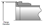
The flange should be inspected for proper diameter and sealing surface quality. See the table below for the flange diameters corresponding to the different sizes.
The sleeve can also be used as a quick gauge of the flange diameter. Visually compare the flange diameter to the tapered surface located at the front end of the sleeve (right behind the flange). The large diameter and small diameters at each end of this surface serve as the maximum and minimum flange diameter limits, respectively.
|
Inch Tube O.D. (in) |
Metric Tube O.D. (mm) |
Flange Diameter (in) |
| 1/4 | 6 | .473 / .502 |
| 3/8 | 10 | .564 / .620 |
| 1/2 | 12 | .709 / .745 |
| 5/8 | 14, 15, 16 | .875 / .923 |
| 3/4 | 18, 20 | 1.048 / 1.097 |
| 1 | 22, 25 | 1.296 / 1.347 |
| 1-1/4 | 28, 30, 32 | 1.549 / 1.597 |
| 1-1/2 | 38 | 1.861 / 1.910 |
Over-flanging will result in tube nut interference, as well as thinning of the flange tube end. Under-flanging reduces the contact area for sealing against the O-ring in the fitting.

Brazing
Brazing is the other method of attaching the sleeve to the tube end. You may have to use brazing if your straight length to the start of a bend is less than the minimum required to use Parker Parflange machine or if you do not have Parflange available.
Brazing can be accomplished by using a multi-flame torch, or an induction brazing unit. During the heating process, the pre-formed braze ring or wire-fed filler material is melted between the tube O.D. and the sleeve I.D., creating a strong bond between the two.
Brazing steps
Step 1 - Determine the tube length allowance:

| Nominal Tube O.D. |
A (in) |
|
| Inch | Metric | |
| 1/4 | 6 | 0.04 |
| 3/8 | 8, 10 | 0.04 |
| 1/2 | 12 | 0.04 |
| 5/8 | 14, 15, 16 | 0.06 |
| 3/4 | 18, 20 | 0.06 |
| 1 | 22, 25 | 0.06 |
| 1-1/4 | 28, 30, 32 | 0.06 |
| 1-1/2 | 35, 38 | 0.06 |
Step 2 - Cleaning the tube end: All oil and oxide build-up must be removed from the tube end for at least the length of the braze joint. Oil may be removed by using an oil-free solvent. Oxide build-up may be removed by pickling or by lightly sanding with an aluminum-free emery paper.
Step 3 - Fixturing the parts for brazing: Care should be taken so the braze fixture allows the sleeve to settle and bottom on the tube completely during heating. Since the Seal-Lok fitting sleeve is designed for a slip fit, this should happen easily. Short tubes can be brazed in the vertical position. On longer tubes, the joint may need to be in the horizontal position, requiring a slight nudge to seat the sleeve on the tube.
Step 4 - Applying flux: Apply proper flux to the tube end (about 1½ sleeve lengths) and sleeve's face and outside surface. Insert appropriate braze ring in the sleeve and place the sleeve on the end of the tube. The flux helps protect the parts from oxidizing and promotes braze flow.
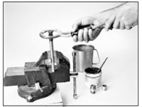 Step 5 - Heating the part: Apply heat uniformly to the joint by using a multi-flame torch (as shown to the right) or with an induction braze unit. Proper brazing involves heating the assembly to brazing temperature and flowing the filler metal through the joint. Heat should be applied broadly and uniformly to the tube as well as the Seal-Lok sleeve. Keep in mind that thicker fitting and tubing sections take longer to heat. The entire assembly should heat to brazing temperature at about the same time. The braze alloy will always flow toward the area of higher temperature. The pre-formed braze ring has been placed inside the joint area-the last area to reach melting temperature. Therefore, when you see the braze material flow to the outside of the joint, you know the joint is complete. If the sleeve does not settle, a slight pressure will cause the sleeve to settle, completing the braze joint.
Step 6 - Cleaning the brazed joint: After stopping heat application, allow about 10 seconds for the braze alloy to solidify. Then, immerse the joint in hot water (approx. 140°F.). To make cleaning easier, add Parker Braze Cleaner to the hot water. This sudden cooling cracks the braze flux residue, making it easier to remove. Any remaining residue can be removed by careful wire brushing, making sure not to scratch the sealing surface of the sleeve.
Step 7 - Corrosion protection after brazing: This is an extremely important step following brazing and even more so following the use of a braze cleaner. Braze cleaners such as Handy and Harman Post Braze Cleaner available from Parker and Bernite 45 (Bernite Products, Inc. 84 New York, Westbury, NY 11500, 516.338.4646) which are used to facilitate the removal of residual flux after brazing, are generally corrosive. The residue left on the surface by the cleaner, especially on the I.D. of the tube, can cause rusting in carbon steel tubes rather quickly, if it is not neutralized. Therefore, it is important to neutralize the cleaner residue after cleaning with a solution such as Bernite 136 - mix 4 ounces of Bernite 136 with one gallon of water. If the brazed parts are not to be used soon after brazing, a coating of rust inhibitors such as WD-403 or SP-3504 (product of CRC Chemicals, USA, Warminister, PA 18974, 215.674.4300) is recommended for the braze and heat affected area.
Inspection of brazing
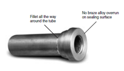 Inspect the braze for a fillet all the way around the tube at the far end (small diameter) of the sleeve. Caution: If there are gaps in the fillet, the joint may not be sound. In this case, rebrazing is recommended. Remove the sleeve and rebraze a new one in its place.
Inspect the sealing surface. There should be no braze alloy overrun or build-up on this surface. If there is build-up, remove it with emery paper, being careful not to scratch the seal surface. If this is not possible, remove the old sleeve and rebraze a new one in its place.
Final installation
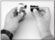 Ensure that the correct O-ring is properly installed in the groove of the fitting, if not already pre-installed by the fitting manufacturer (Parker provides Seal-Lok fittings with pre-installed O-rings). Since Seal-Lok is machined with the captive O-ring groove (CORG), it is recommended that a CORG assembly tool be utilized, as shown to the left. To properly use the assembly tool, follow these steps:
-
Position the O-ring inside the CORG assembly tool against the pusher.
- Position the tool over the Seal-Lok tube end until the end is bottomed in the tool.
- Push the plunger of the tool until the O-ring is inserted and seated into the groove.
Place the tube assembly against the fitting body so that the flat face of the flange tube (or braze sleeve) comes in full contact with the O-ring. Thread the nut onto the fitting body by hand and tighten it to the recommended torque - see the tables below for Seal-Lok and Seal-Lok Lite. If torque wrenches are not available, an alternate method of assembly is the Flats From Wrench Resistance (F.F.W.R.) method. Wrench tighten the nut onto the fitting body until light wrench resistance is reached. Tighten further to the appropriate F.F.W.R. value. You may need two wrenches to prevent the fitting from moving during assembly.
The torque method of assembly is the preferred method of assembly for Seal-Lok and Seal-Lok Lite fittings. It reduces the risk of human error during assembly that is more prevalent in the Flats From Wrench Resistance (F.F.W.R.) method. To ensure the most accurate assembly of the Seal-Lok fitting, it is strongly recommended that the torque method be utilized.
| O.D. |
SAE Dash Size |
Tube Side Thread Size (UN/UNF) |
Tube Side Assembly Torque (+10% -0%) |
Flats from Wrench Resistance (FFWR) |
||||
| (in) | (mm) | in-lb | ft-lb | N-m |
Tube Nuts |
Swivel & Hose Ends |
||
| 1/4 | 6 | -4 | 9/16-18 | 220 | 18 | 25 | 1/4 to 1/2 | 1/2 to 3/4 |
| 3/8 | 8, 10 | -6 | 11/16-16 | 360 | 30 | 40 | 1/4 to 1/2 | 1/2 to 3/4 |
| 1/2 | 12 | -8 | 13/16-16 | 480 | 40 | 55 | 1/4 to 1/2 | 1/2 to 3/4 |
| 5/8 | 14, 15, 16 | -10 | 1-14 | - | 60 | 80 | 1/4 to 1/2 | 1/2 to 3/4 |
| 3/4 | 18, 20 | -12 | 1 3/16-12 | - | 85 | 115 | 1/4 to 1/2 | 1/3 to 1/2 |
| 1 | 22, 25 | -16 | 1 7/16-12 | - | 110 | 150 | 1/4 to 1/2 | 1/3 to 1/2 |
| 1-1/4 | 28, 30, 32 | -20 | 1 11/16-12 | - | 150 | 205 | 1/4 to 1/2 | 1/3 to 1/2 |
| 1-1/2 | 35, 38 | -24 | 2-12 | - | 230 | 315 | 1/4 to 1/2 | 1/3 to 1/2 |
| 2 | 50 | -32 | 2 1/2-12 | - | 375 | 510 | 1/4 to 1/2 | 1/3 to 1/2 |
We Want You to Understand The Products You Use
We're specialists in fluid connectors. If we have not answered your questions here, please use the form on this page to get your answers.