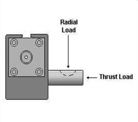
Shaft Loads
Design Torque
Design torque represents the maximum torque than an actuator must supply in an application. This maximum is the greater of the Demand Torque or the Cushion Torque. If the demand torque exceeds what the actuator can supply, the actuator will either move too slowly or stall. If the cushion torque is too high, the actuator may be damaged by excessive pressure. Demand torque and cushion torque are defined below in terms of load, friction and acceleration torque, along with equations for calculating demand torque and cushion torque for some general applications.
T - Torque
The amount of turning effort exerted by a rotary actuator.
TD - Demand Torque
The torque required from the actuator to do the job - the sum of the load torque, friction torque and acceleration torque, multiplied by an appropriate design factor. Design factors vary with the applications and the designers' knowledge.
TD = Tα + Tf + TL
TL - Load Torque
The torque required to equal the weight or force of the load. The load torque term is intended to encompass all torque components that aren't included in the friction or acceleration terms.
Tf - Friction Torque
The torque required to overcome friction between any moving parts, especially bearing surfaces.
Tf = μWr
Tα - Acceleration Torque
The torque required to overcome the inertia of the load in order to provide a required acceleration or deceleration. See the Rotary Actuators Basic Equations page for more information regarding mass moments of inertia and equations for determining acceleration (α).
Tα = Iα
TC - Cushion Torque
The torque that the actuator must apply to provide a required deceleration. This torque is generated by restricting the flow out of the actuator (meter-out) to create a back pressure which decelerates the load. This back pressure/deceleration often must overcome both the inertia of the load and the driving pressure (system pressure) from the pump.
TC = Tα + PrV/θ - Tf ± TL
The friction torque Tf reduces the torque the actuator must apply to stop the load. The load torque TL may add to, or subtract from the torque required from the actuator, depending upon the orientation of the load torque. For example, a weight being swung upward would result in a load torque that is subtracted.
WARNING: Rapid deceleration can cause high pressure intensification at the outlet of the actuator. Always insure that cushion pressure does not exceed the manufacturer's pressure rating for the actuator.
KE - Kinetic Energy (1/2 Jmω2)
The amount of energy that a rotating load has. The rotator must be able to stop the load. All products have kinetic energy rating tables. Choose the appropriate deceleration option (i.e., bumper, cushions, shock absorbers, etc.) that meets or exceeds the kinetic energy of the load.
|
Example 1: TD = Tα + Tf + TL Tα = 0 Tf = 0 TL = (500 lb)(10 in) = 5,000 lb-in TD = 5,000 lb-in |
 |
|
Example 2: (The 500 lb rotating index table is supported by bearings with a coefficient of friction of 0.25. The table's acceleration is at 2 rad/sec2. The table's mass moment of inertia is 2,330 lb-in-sec2.) TD = Tα + Tf + TL Tα = Iα = (2,330 lbs-in-sec2)(2/sec2) = 4,660 lb-in Tf = μWrb = 0.25 (500 lb)(55 in) = 6,880 lb-in TL = 0 TD = 4,660 lb-in + 6,880 lb-in = 11,540 lb-in |
 |
|
Example 3: TD = Tα + Tf + TL Tα = 0 Tf = 0 TL = (500 lb)(10 in) = 5,000 lb-in TD = 5,000 lb-in |
 |
Mass Moments of Inertia Equations Table
|
Rectangular Prism Ix = 1/12m(b2 + c2) Iy = 1/12m(c2 + a2) Iz = 1/12m(a2 + b2 ) |
 |
Circular Cylinder Ix = 1/2ma2 Iy = Iz = 1/2m(3a2 + L2)
|
 |
|
Thin Rectangular Plate Ix = 1/12m(b2 + c2) Iy = 1/12mc2 Iz = 1/12mb2 |
 |
Circular Cone Ix = 3/10ma2 Iy = Iz = 3/5m(1/4a2 + h2)
|
 |
|
Sphere Ix = Iy = Iz = 2/5ma2 |
 |
Thin Disk Ix = 1/2mr2 Iy = Iz = 1/4mr2 |
 |
|
Parallel Axis Theorem Ip = ⌈ + md2
|
 |
Ip = Mass moment of inertia about an axis parallel to a centroidal axis ⌈ = Mass moment of inertia about a centroidal axis m = Mass d = Distance between axes |
|
Where:
t = time
θ = angular position
ωt = angular velocity at time = t
ω0 = angular velocity at time = 0
α = angular acceleration
When Acceleration Is Constant:
θ = ω0t + 1/2αt2 ; α = 2θ/t2
θ = ω0t + 1/2ωtt ; α = (ωt - ω0)2/2θ
ω = (ω02 + 2αθ)1/2 ; α = (ωt - ω0)/t
When Velocity Is Constant:
θ = ωt
Basic Velocity, Acceleration, Kinetic Energy and Torque Equations
(The equations below are based on triangular velocity profile.)
Where:
Θ = Angle of rotation (degrees)
t = Time to rotate through Θ (sec)
ω = Angular velocity, radians/sec
α = Angular accelerations (radians/sec2)
WL = Weight of load (lbf)
Ta = Torque to accelerate load (lb-in)
Us = Coefficient of static friction
Jm* = Rotational mass moment of inertia (lb-in-sec2)
Tf = Torque to overcome friction (lb-in)
TL = Torque to overcome effects of gravity
* Use "I" values from the Mass Moments of Inertia table
Equations:
ωmax = 0.35 x Θ/t
α = ωmax2/ (Θ/57.3)
α = ωmax/(t/2)
K.E. = 1/2 Jmω2
Ta = α x Jm
Tf = W x Us x (Distance from pivot point to center of external bearings)
TL = (Torque arm length to C.G. of load) x WL x cos (Φ)
(Where Φ = Angle between torque arm and horizontal plane)
Coefficients of Friction
| Material* | μs | μk |
| Steel on steel | 0.80 | 0.40 |
| Steel on steel (lubricated) | 0.16 | 0.03 |
| Aluminum on steel | 0.45 | 0.30 |
| Copper on steel | 0.22 | 0.22 |
| Brass on steel | 0.35 | 0.19 |
| PTFE on steel | 0.04 | 0.04 |
*Dry contact unless noted